New Features and Improvements
In past months several enhancements have been implemented in RM Bridge V8i version. Due to the variety of new functions we decided to create a short summary of the comprehensive functionality in form of document.
We are encouraging you to accept the challenge of using them and giving us feedback of your experience as well as new ideas, which will serve you during your bridge analysis and design.
Find this article also as PDF in different languages:
See also What is New & Changed in RM Bridge V8i v08.10.12.01
Pre and Post-processing
Results Viewer is a new Post-Processing tool implemented in RM Bridge. It combines the simplicity of using predefined frames from CAD programs with the detailed and exact options of RM result display. Any kind of frame can be drawn with certain levels or layers used to define the areas for different result presentations.
![]()
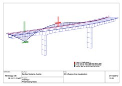
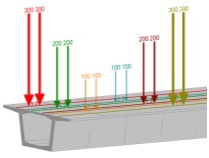
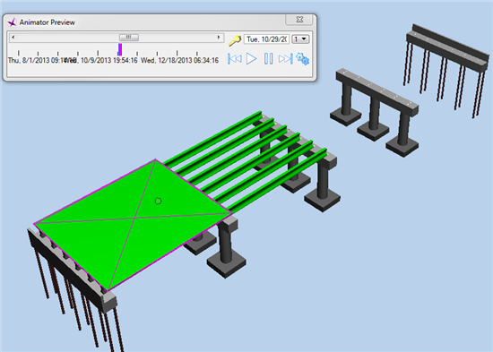
Live Load Visualization is one of many new features, available within Results Viewer.
![]()
It enables graphical display of geometric position of defined Traffic Lanes and Load Trains in 3D drawing as well as display of influence lines together with Load Trains. Load Trains are displayed at the most unfavourable positions, producing the worst case minimum and maximum responses for any result component. The definition of the 2D Influence line display was also revised: only selected internal forces and displacements for a certain element will be displayed. Assemblies are new groups of elements, which will facilitate pre- and post-processing within RM Bridge. Different analysis elements (beam elements, tendons, cables, etc.) can be grouped (automatically and manually) into assemblies and they can be used for different purposes. Assemblies can also replace element series for purposes of Load Definition.
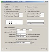
Macros have been implemented for easier load definition:
- Traffic Loads
- Load Combinations
- Load Trains
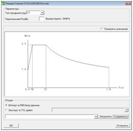
- Response Spectra
![]()
They are according to different International standards (BS5400 Part2, BD37/01, HK Standard, AASHTO LRFD and ASD, JTG, Canada, EN, Korean, Norway, Sweden, IRC, SNIP, AS5100, Spain, NBR Brazilian standard, etc).
Traffic Load macros create beside Load Trains also all necessary Schedule actions for evaluation and superposition of those results in the final traffic envelope(s).
Macros for Load Combinations, Load Trains and Response Spectra create complete definition of Load Combination Table, Load Trains and Response Spectrum diagram(s) according to selected standard. Different macros can also be used for creating different types of plot containers, such as plot containers for structure, geometry, Load Case results, Superposition Results and Eigenforms.
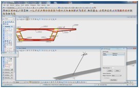
In Modeler several enhancements have been done:
- new construction line types are added in cross-section definition
- new predefined cross-sections are added to the cross-section catalogue
- automatically numbering of elements and nodes is done, when multiple parts are used
- moving a node of a defined FE element is possible
- importing simple cross-sections defined by CAD programs
- many other smaller enhancements ...
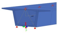
In Analyzer several pre and post-processing enhancements were also introduced:
- Support conditionscan be displayed in general 3D view.
- Element propertiescan be seen, but also edited.
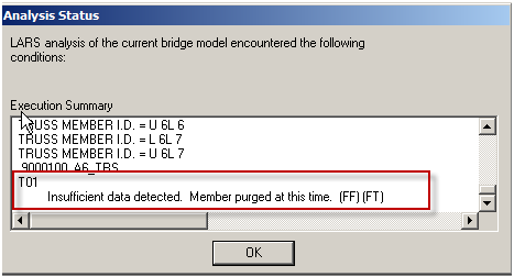
- Results (displacements, internal forces and stresses) for chosen Load Cases/Envelopes can be interactively selected in the left bottom display window and viewed.
![]()
BrIM – Bridge Information Modeling
Saving engineering time and avoiding re-entering data is one of the main BrIM goals.
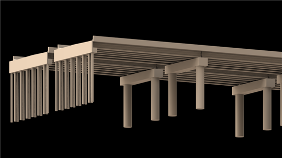
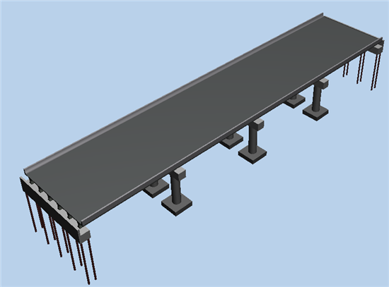
RM Bridge Modeler allows importing complete bridge axis information (horizontal and vertical geometry). This axis can be used as alignment and profile for the bridge object. Currently Land XML format is imported, what connects RM Bridge with other Bentley road/rail applications: MX-Road, InRoads, RailTrack.
![]()
By same approach the complete terrain model can be imported. It can be used for visualization purposes.
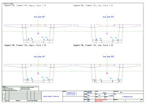
RM Bridge produces plot files, which are result of structural modeling, analysis and design of bridge structure. Those files can be defined as DGN, but also DWG format.
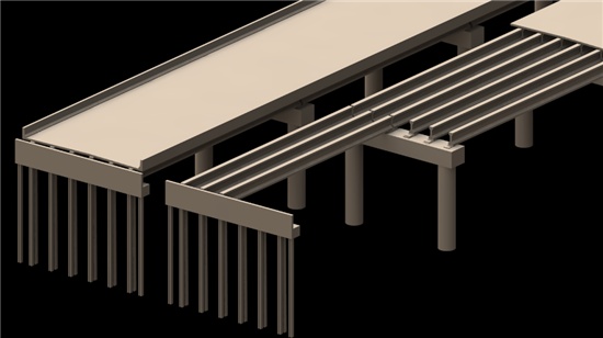
RM Draw Manager is an automated drawing production tool. The drawing generation is based on “Templates” describing the Layout of the individual drawing, and “Masters” describing the content of the drawing: complete 3D model, 3D model of tendon geometry, elevation and plan view of the axis, tendon scheme and tendon layout, cross-sections, shop drawings, etc.
![]()
Context mouse menu enables several good tools – also export of current 3D bridge view to DGN file, which can be further on manipulated by Microstation.
Additional interoperability within the Bentley BrIM group was accomplished through connection between RM Bridge as an analysis and design software and Power Rebar as a powerful general reinforcement detailing product offered by Bentley for creating reinforcement drawings for concrete structures, also bridges.
![]()
The link between these two products considerably raises the efficiency of the detailing process. The data transferred between RM Bridge and Power Rebar includes Model geometry, Tendon geometry and Reinforcement requirement. In Power Rebar, the model and tendon (duct) geometry may directly be used as reference objects to simplify geometry definition. The reinforcement requirement data is generalized data (total area of required reinforcing steel) to be translated into actual bars (diameter, length, shape) and spacing.
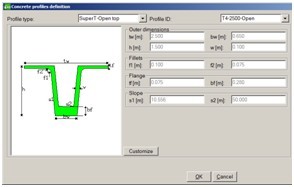
RM Wizards provide the complete RM solution for simple bridges. For different types of bridges different Wizards exist: Pre-Cast bridges, Reinforced slab bridges, Composite bridges (steel with concrete or orthotropic deck) and Hollow box bridges. The superstructure and substructure geometry as well as the load definition will be input in form of templates that simplify the process. Once the input is finalized, a complete analysis and design of the bridge is performed according to the selected standard. At the end of the analysis and design a complete report in form of a PDF file is generated.
![]()
In the Pre-Cast wizard now the geometry of Super-T Beam bridges according to Australian Standard can also be defined.
Technical enhancements
Steel and Composite Design Checks are one of the major technical enhancements in RM Bridge lately. Local steel phenomena like flexural buckling, torsional-flexural buckling, local buckling, lateral-torsional buckling are considered.
Some additional proof checking actions has been added within RM Bridge. They work completely in accordance with respective design checks (EN, AASHTO and SNIP).
![]()
Steel Checks require some additional geometrical input data: definition of slender cross-section parts need to be prepared in Modeler already. By cross-section definition a new type of Reference Set "Slender parts" needs to be used. Material properties are upgraded as well.
First ultimate resistances are calculated for different impact categories (tension, compression, bending and shear). Afterwards the check for arbitrary stressing states is done by comparing the ultimate state with the design resistances using appropriate interaction formulas. In case of a primary stressing state in the section (e.g. in stage-wise built composite sections) the actual design resistance must be recalculated with considering the primary stresses before the interaction formulas can be applied.
New tendon type was introduced - Pre-Tensioned tendon. In comparison with other tendon types the input is different – the nominal pre-stressing force (force in the tendon before cutting the connection to the external anchor points) is defined directly when creating/modifying the tendon. Same follows also for definition of sleeve lengths at begin and at end.
Pre-Tens is a new Schedule action which activates Pre-tensioned tendons (strands).
![]()
The action simulates the process of removing the formwork from prefabricated girders and cutting the connection of the strands to external anchor points.
The losses due to elastic shortening are calculated and the resulting internal force state (primary state) is stored in the specified load case.
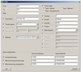
A new feature for tendon geometry definition is added: it is possible to input eccentricities or to set one or both of them to free. Eccentricities will be automatically calculated, what allows definition of independent points in plan and elevation view.
![]()
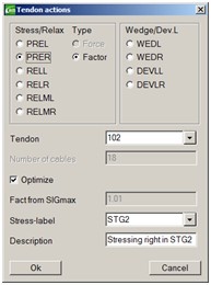
Automatic optimization of the post-tensioning sequence is now also possible. The program automatically calculates the stressing forces such that in every intermediate tensioning step and at the end after the wedge slip the allowable values are not exceeded.
Load Train definition and calculation now allows also defining Load Train with two constant uniform loads with constant or variable distance between them.
Additional also 2D Load Trains can be defined. This means that area load with constant or variable length can be defined as well as tire pressure (at one axis) in form of two area loads with constant length and width and certain transversal distance between both. However, the input is still code oriented, so in the standard provided axis load must be defined and recalculation to area load is done automatically.
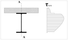
Options Joined and Split have been made available for shear force results.
![]()
The function Joined is performed straight-forward on force level. The function Split was provided as “reasonable” engineering solution based on the assumption that shear forces are the dominating terms and torsion moments play a minor role. I.e. shear forces are split in accordance with “effective” shear areas calculated by integrating the shear flow in the composite section over the individual parts and the effect of the torsional moment is adjusted accordingly. The new approach allows for a consistent use of the Join and Split functions throughout the program, especially in the context of the new functionality for steel design.
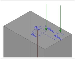
Consideration of an additional eccentricity of compression forces in piers for performing ultimate load capacity check and reinforcement design is required by several design codes.
![]()
Eccentricity depends of slenderness, i.e. of relevant buckling length and cross-section properties. Parameters used for the calculation of additional eccentricity are code dependent.
To consider such additional eccentricity, when performing reinforcement design ("UltChk" action with option "Rein") in RM Bridge an RM Set of type PIERDIM must be defined and referenced in the corresponding action. This RM Set contains a list of elements where additional eccentricity shall be calculated and taken into account. Consideration of such an eccentricity is now possible also according to Chinese Highway Code – JTG.
In the last decade the mode superposition methods CQC (Complete Quadratic Combination) and the variant CQCX have become standard for earthquake analyses based on the response spectrum method. RM Bridge offers in addition a special method for getting the maxima and minima of the internal force results as well as concomitant values (called TDV superposition method). This method requires triangulization of the correlation matrix which is a complex mathematical task. In previous program versions this functionality had various deficiencies (not available for CQCX, very slow, unstable in different circumstances, …). This functionality has now been considerably improved, i.e. made available for all mode superposition methods, stability of the mathematical process and computation speed considerably improved.
New load type Node velocity for Time Integration Analysis (Ship Impact) has been implemented.
Localization
Extensive localization for Russia has been made in RM Bridge – the complete graphical user interface is available in Russian Language - including Cyrillic letters. This also applies to several manuals and quick help.
![]()
The material database is improved with Russian Material for concrete, steel and pre-stressing steel. All standard dependent material properties, requested for analysis and design code checks, are stored. Time dependent functions - creep and shrinkage of concrete and relaxation of pre-stressing steel are included.
Design Checks according to SNiP for concrete are implemented as well: Fibre Stress Check and Ultimate Load Capacity Check (including reinforcement design).
![]()
Steel and Composite design checks, as mentioned in Technical enhancements, are available for SNiP. Local steel phenomena like flexural buckling, torsional-flexural buckling, local buckling, lateral-torsional buckling are considered.
Several templates according to SNiP for easier modeling and load preparation are available:
- Russian standard steel profiles according to GOST
- Load Trains
- Response Spectra
- Load Combinations
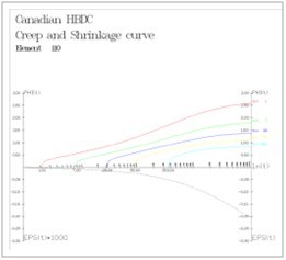
Implementation of Canadian code is also one of news in RM Bridge.
![]()
The scope of this implementation comprises standard depended design code checks and materials. The material database was expanded with Canadian materials including time dependent material properties (creep & shrinkage and steel relaxation).
Implemented design code checks according to Canadian code are:
- Ultimate load capacity check (including reinforcement calculation)
- Shear check
- Crack check
Many additional localization features are implemented in RM Bridge:
- Norwegian shear capacity for reinforced/post-tensioned concrete according to local EN NAD
- Time dependent concrete properties according to Australian standard.
- JTG Load Combination Template with combinations for deformation checks
- Extended French graphical user interface
- Gust factor according to EC for wind load calculation
- Implementation of Brazilian materials and Traffic loads
- And many others
![]()